Introduction
Some time ago, I saw a ‘power station’ type of thing. For those uninitiated, they are a beefed-up versions of a power bank, with 12V DC and 230V AC-like[1] outputs. I wanted to have a thing like that, but tailored to my demands.
Requirements
- Battery capacity enough to survive a light use during a weekend without electricity
- 12V output for various devices like a car fridge
- 13,8V output for my ham radio
- A set of USB outputs (both USB A and USB C) to charge small devices like phones
The choice of 12V and 13,8V outputs bumped up the minimal battery pack voltage, but the real deal was USB-C. The standard[2] says, that USB Power Delivery supports charging not only with the usual 5V/2A, but also 9V/15V/20V on 3A. This would let me charge my laptop, but also bumped up the minimal voltage.
Battery pack
Having said that, the minimal output voltage was around 20V, plus a margin for a buck DC-DC converter. The best I could do was 6S li-ion, which gave me 25,2V fully charged, up to around 22V during most of the discharge cycle.
Next question was the current.
By design, I chose 5A, as that would give me 100W, which is well over a typical use case. I can charge a laptop and a phone at once and still have a little bit of margin.
As the expected current isn’t so big for li-ion cells (the vape ones have insane maximal currents), I opted for high-capacity, low-current cells. LG INR18650 M29 were the ones of choosing. 6A current with capacity of 2800mAh is a good deal.
Last question was, how many of them. Well… by a napkin calculation I chose 5P. In total, 30 cells. I bough a few more in case there were some odd capacities.
I ordered the cells and a battery tester. Now comes the boring part. Charge all of them, then discharge one by one (fortunately, I bought a 4-slot battery tester) and record each one’s capacity. I pushed all the measured capacities into rePackr to group them. Sidenote: you have to remember, that BMS can disconnect your pack to prevent overcharging when the first parallel group is fully charged. This means you need to match the groups to achieve optimal capacity.
Having had sorted and matched the groups, it was time to put the cells into holders (with paper-like separators to avoid shorts). I opted for a brick shape (6x5 rectangle), which later turned out to be a mistake – this shape is quite hard to fit into a case.
With a complete block of cells, it was time to connect them together with a spot welder.
If you have any love in your heart, be careful with Li-ion cells! They are very spicy and one welding mistake can create a nasty fire. To avoid most of the fires, check the prospected welds with a multimeter: if you see any voltage between cells you’d like to connect, STOP, as this would blow up (literally).
Here’s everything welded together, with kapton tape and BMS soldered.
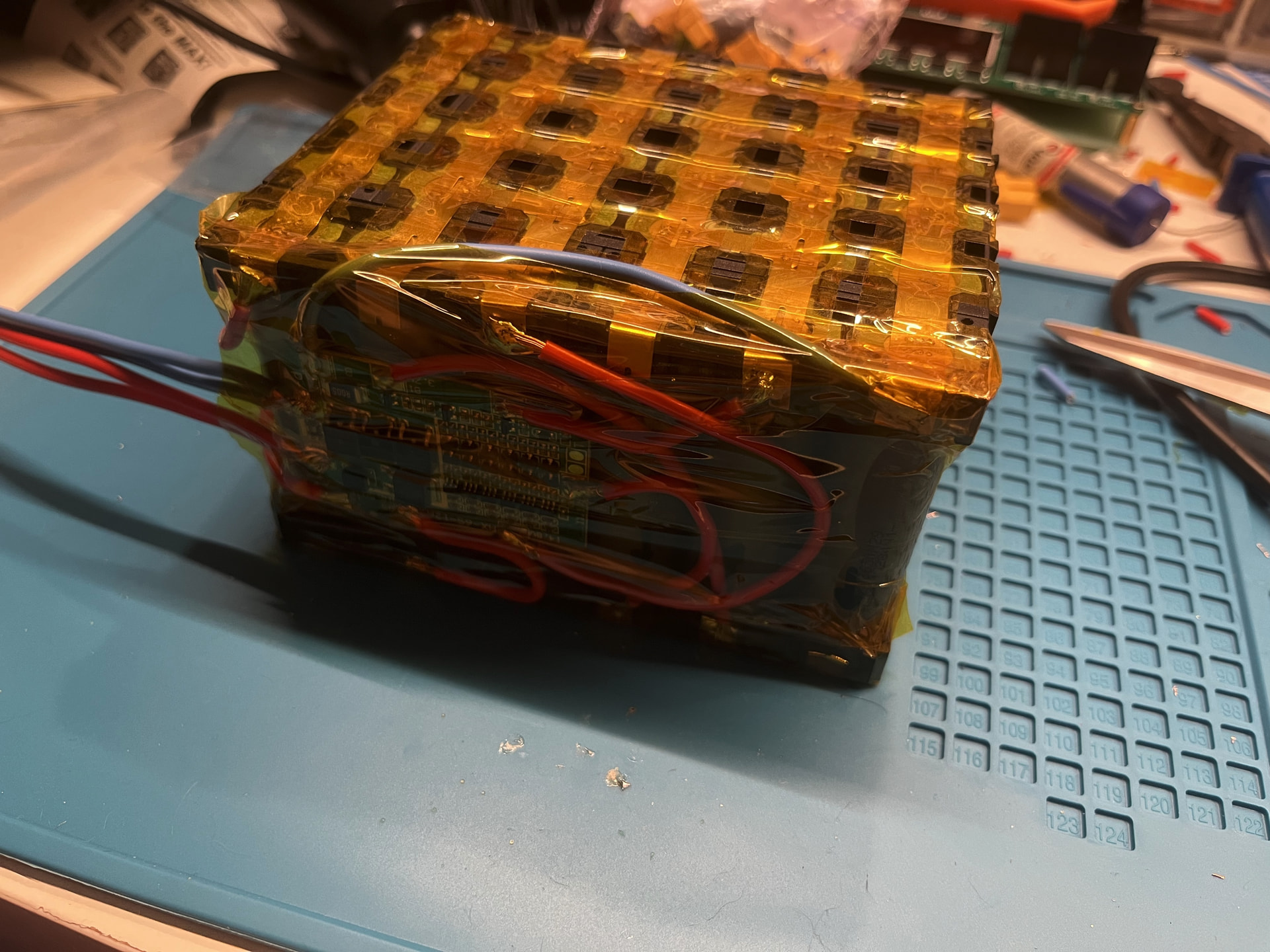
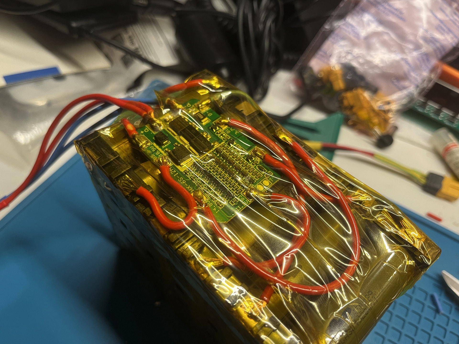
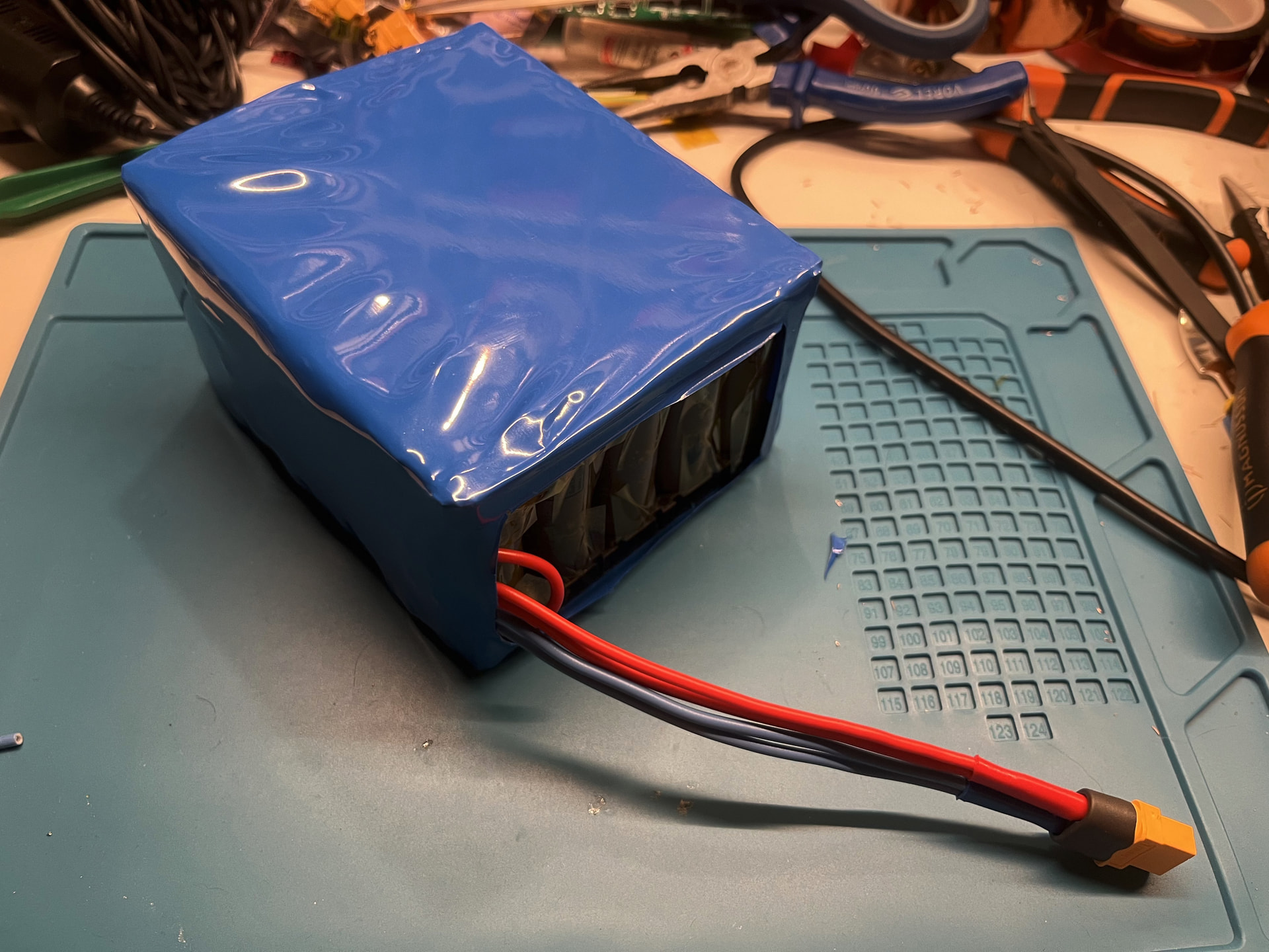
Now some heat-shrink for some basic protection.
Power adapters, first iteration
First iteration consisted of a plexiglass frame and hex nuts. I didn’t look too good, but it was fine for some time.
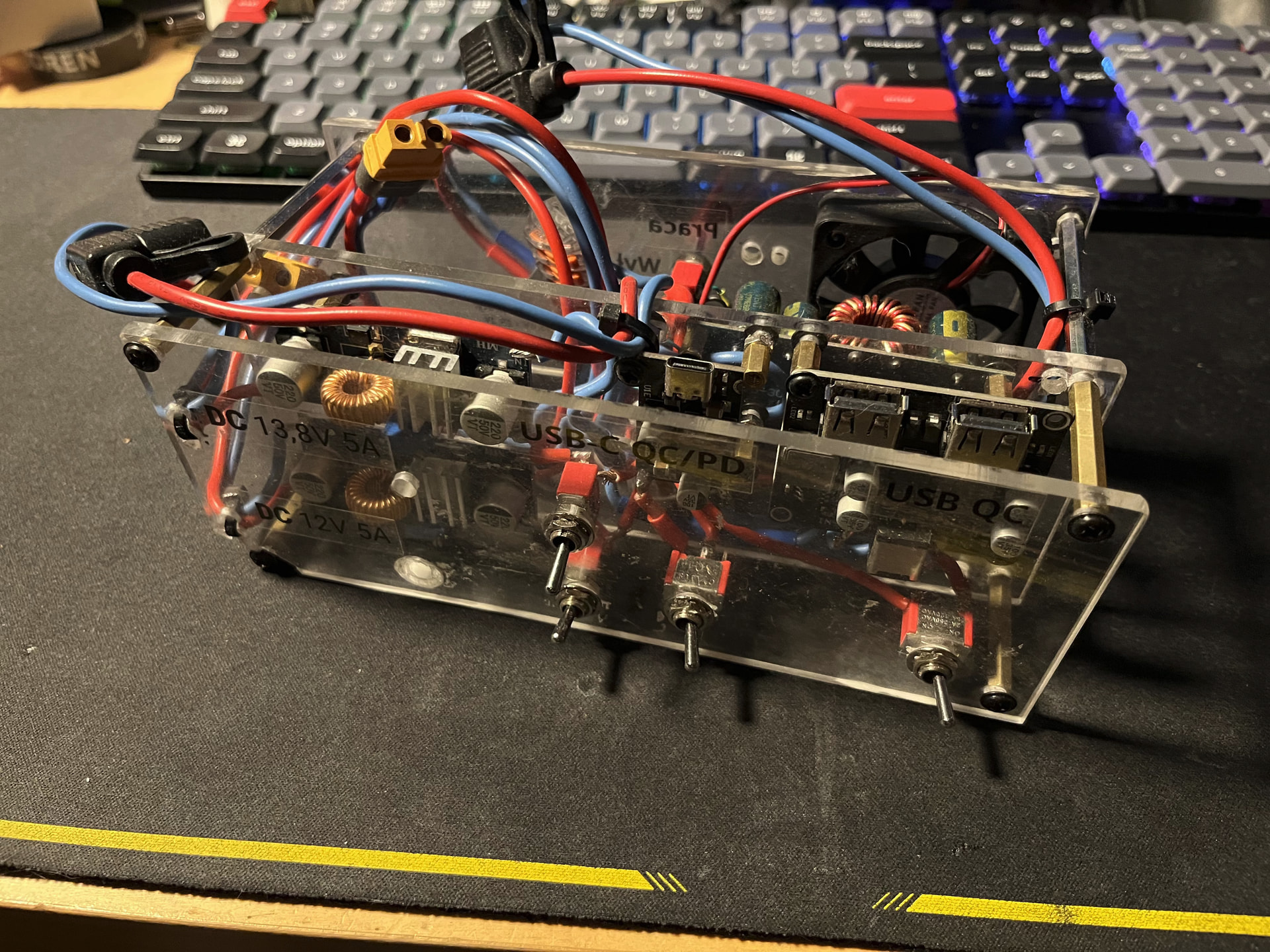
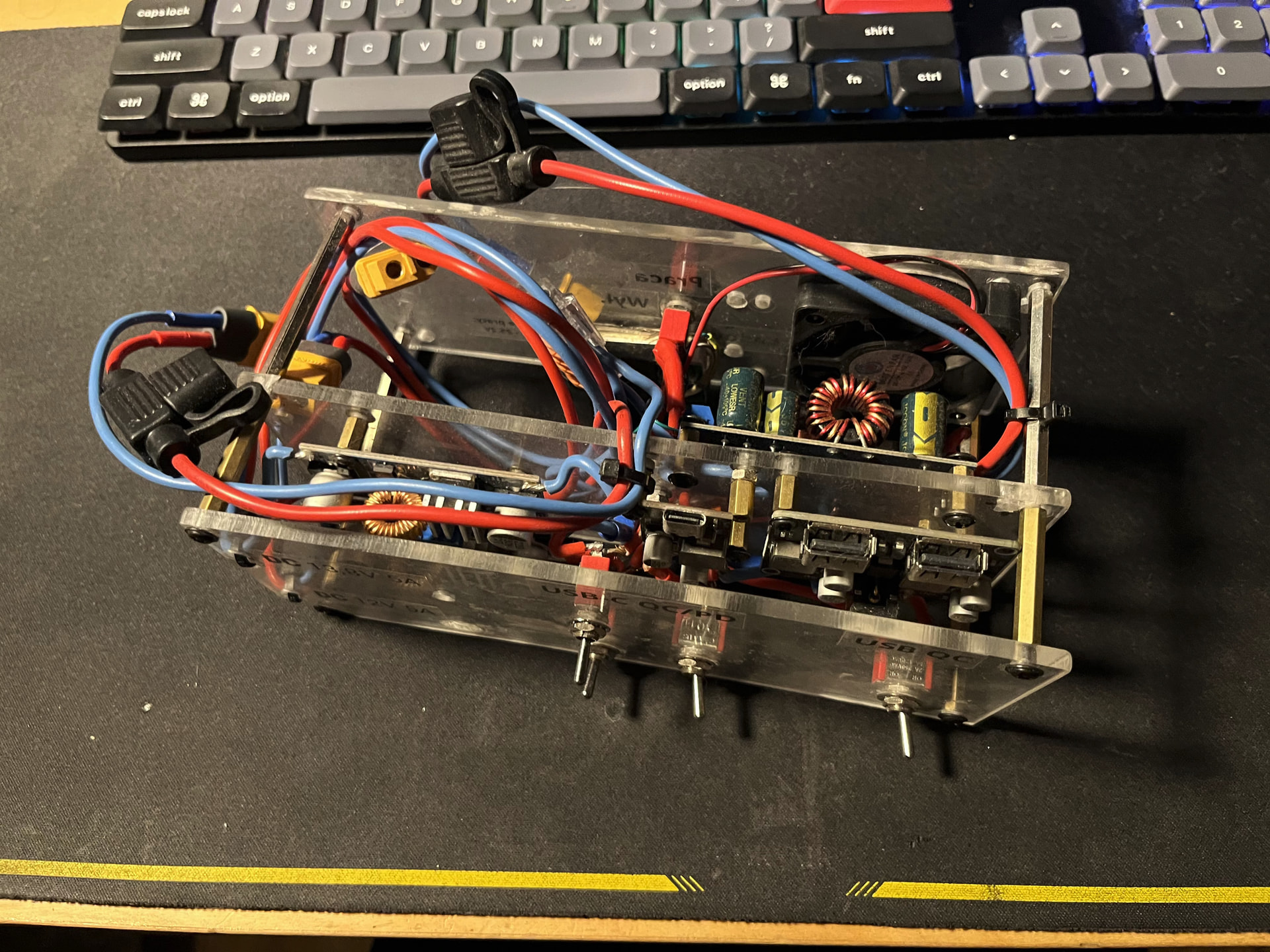
An important addition was a buck-boost converter to charge the battery. Now, I no longer have to disconnect and charge it through a dedicated charger. Any sufficiently capable power source is enough.
Power adapters, second iteration
Let’s be honest. This contraption looked terrible. Cue about one year forward, I learned some Autodesk Fusion and made this little model:
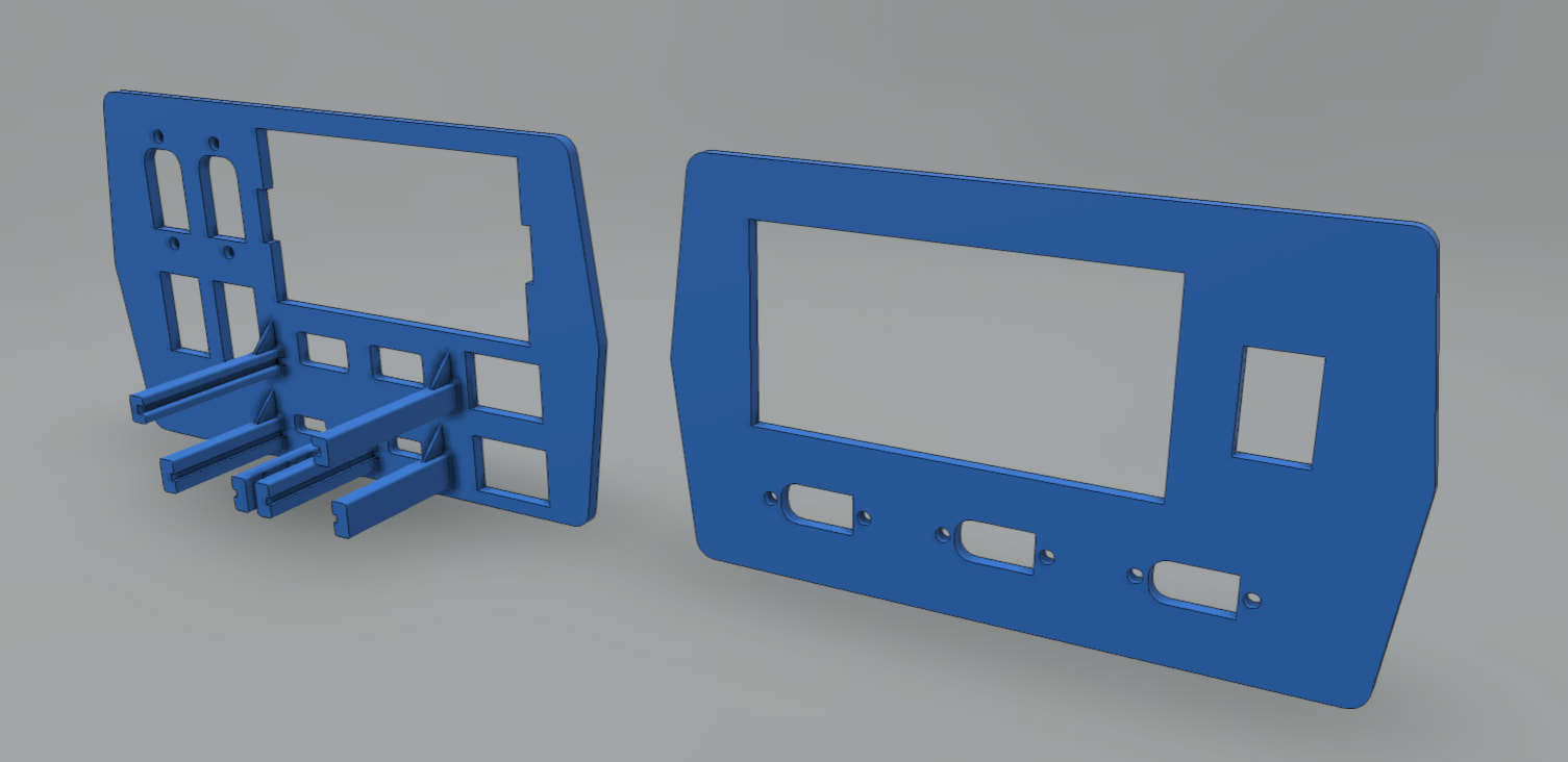
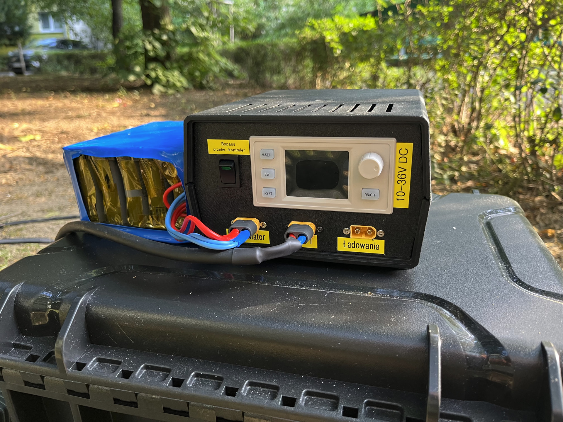
It’s a front and back panel matching this enclosure. An upside of this choice is, that I don’t have to design side panels, screw mounts and fit it together hoping for the whole box not to collapse. Adding some switches and cheap-but-not-so-much Chinese buck-boost controller, I’ve got it all working. Now the whole set is:
- 2x USB-C adapter with PD up to 60W
- 2x regulated 5A buck converter
- one for 12V
- one for 13,8V
- 1x USB-A adapter with two sockets, supporting Qualcomm QC
- 1x “Battery controller” – a bit too smart, but it can:
- (dis)connect the battery if it believes something is wrong with voltage/current/temperature/charge status
- display current voltage, power consumption
- 1x buck-boost controller to charge the battery pack
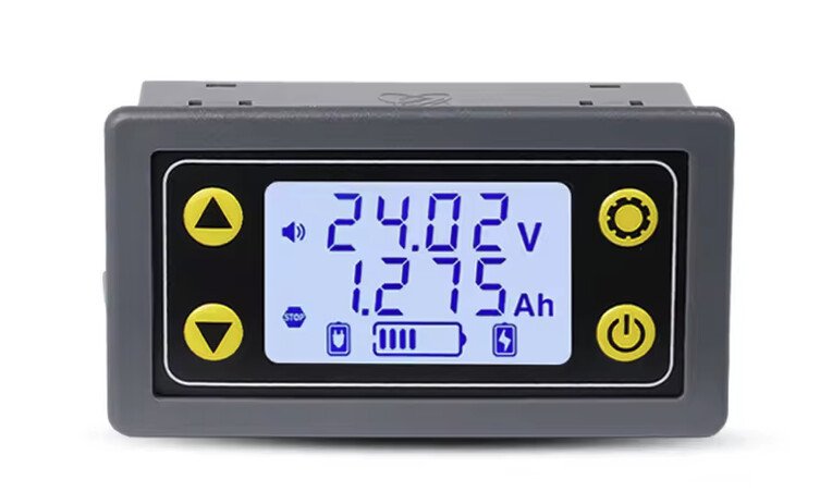
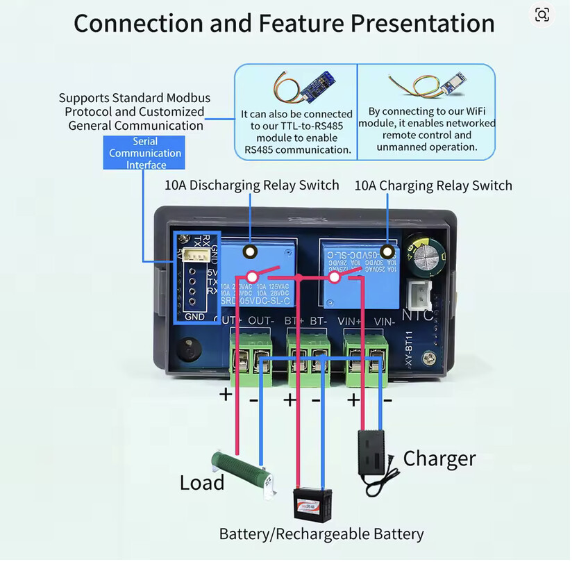
Battery controller
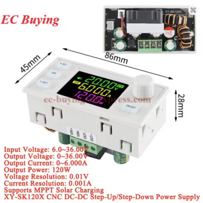
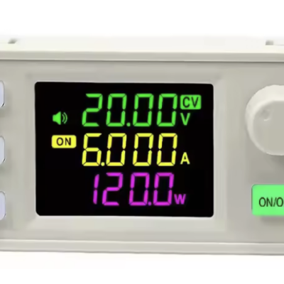
Buck-boost converter with “MPPT”
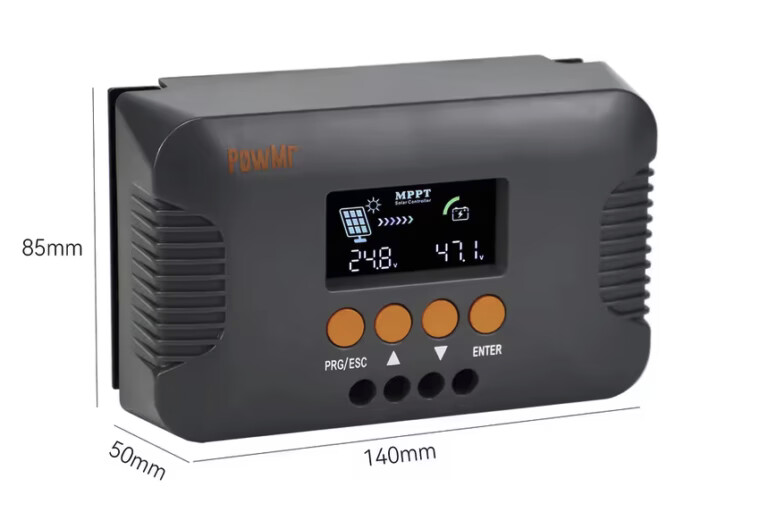
PV panel and MPPT converter
I should have said that earlier, but the whole ‘second iteration’ project was to fit also a PV panel. My next goal was to have a portable fridge, powered from the sun – good for camping trips.
I bought the buck-boost controller in hope the manufacturer didn’t lie about its “MPPT capability”. Spoiler alert: they lied.
The dream setup was one converter, which could work both with an AC adaptor (I’m using a Dell laptop charger by the way) and a PV panel.
For those uninitiated, solar panels are weird beasts. You can read they can be modeled as a “current source”, but that’s not exactly true, as they are non-linear.
Depending on the conditions (sun exposure, clouds, time etc.) they can generate variable amount of current. They have some open-loop voltage, which usually doesn’t change much depending on the insolation. However, the more current you try to pull, the more their voltage drops. As P=VI, you can easily see this reduces power. On the other side, if you want to get any power from the panel, you need to pull some current after all.
Here comes MPPT converter. It measures voltage and current across some sensible range (and it have to do it not just once, but in some intervals – sunlight tend to change!) and pull the current which has the optimal output power.
Back to the shopping!
One problem is, that most MPPT converters are optimized for 12V or 24V lead-acid batteries and generate suitable output, as well as voltage characteristics (boost charge, then lower float charge). I managed to find a converter which supplies up to 25,2V for my battery pack.
Finished thing
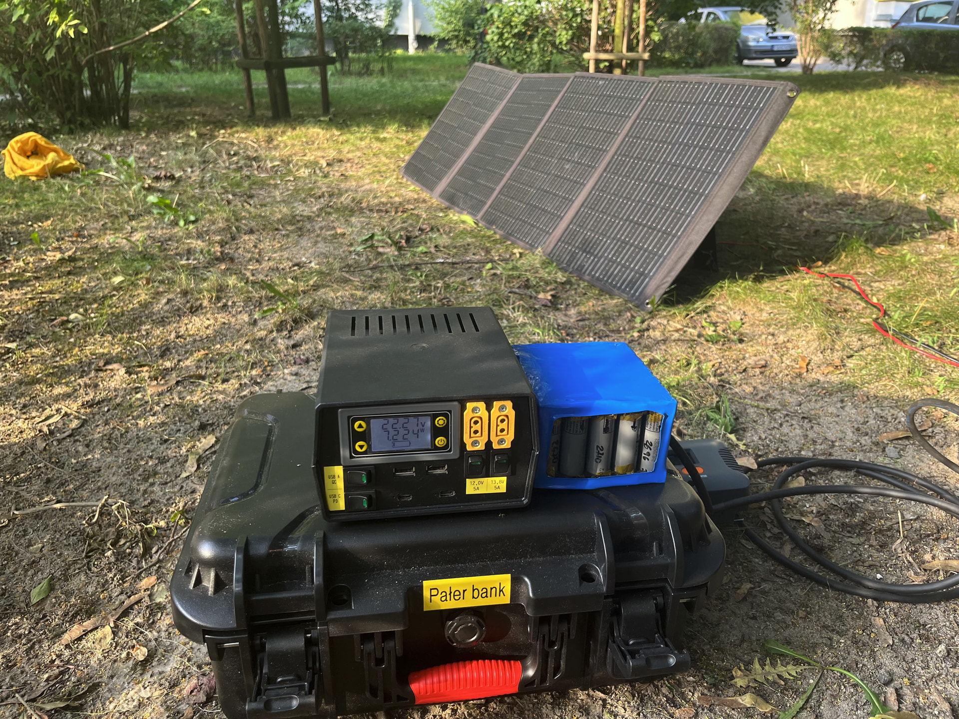
Now, some assembly. I’ll spare you seeing a rats’ nest of wires by just letting you know I’m so glad I used as many crimped ferrules and terminals, which made the whole thing a little bit more serviceable, in case any of the modules failed.
Here’s The Thing, including a PV panel and a case.
As a last part, a huge thank you to everyone at Hackerspace who helped me design and review the model, then 3D print it!
AC-like, because those inverters tend to generate only something roughly resembling a sine wave – often a staircase waveform, or, for very cheap devices, straight out square wave. ↩︎
Let’s face it, I was too afraid to read hundreds-pages-long documents, so here’s a link to Wikipedia: USB hardware - Wikipedia ↩︎